Here, some of the distance protection schemes are described. The system used is consists of Four substations (Station A, Station B, Station C, and Station D)
T_L_BC:
Transmission Line between Station B and Station C starting at Station B and ends at Station C
T_L_CB :
Transmission Line between Station C, and Station B starting at Station C and ends at Station B
T_L_BC_T1:
First Stage of Distance Relay installed at station B to protect line BC with time delay T1
T_L_BC_T2:
Second Stage of Distance Relay installed at station B to protect line BC with time delay T2
T_L_BC_T3:
Third Stage of Distance Relay installed at station B to protect line BC with time delay T3
T_L_CB_T1:
First Stage of Distance Relay installed at station C to protect line CB with time delay T1
T_L_CB_T2:
Second Stage of Distance Relay installed at station C to protect line CB with time delay T2
T_L_CB_T3:
Third Stage of Distance Relay installed at station C to protect line CB with time delay T3
The first example of distance schemes is shown in figure (29). It shows a transmission line BC, and this transmission line is protected by two distance relays (one at each end). Every relay consists of three stages in the forward direction with three different time delays T1, T2, and T3.

The second example figure (30) shows a fault nearly at the mid point of the transmission line BC. This fault is classified by both relays as a first stage fault ( fault at Zone1). The two circuit breakers associated with the two relays will be tripped by a time delay equal to T1 (almost T1 is zero).

The third example figure (31) shows a fault near to substation C. This fault is classified by relay C as a first stage fault (fault at Zone1), and by relay B as a second stage fault (fault at Zone2). Relay C will operate by a time delay equal to T1, and the fault is still feed by station B which will operate by a time delay equal to T2 (almost T2 = 0.45 : 0.5 second).
Sorry , image not found !
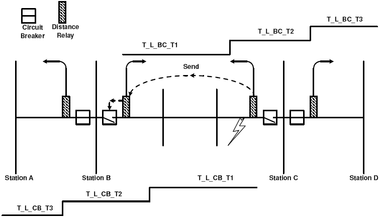
The fourth example figure (32) shows a fault like to the previous example but with applying the under reach scheme. In this example the circuit breaker at station C will be tripped with a time delay equal to T1.
In this case, the operation of relay B depends on two condition
In this case, the operation of relay B depends on two condition
1- Starting Zone2 of relay B
2- Receive signal from relay C ( due to first stage tripping )
The previous two condition will lead relay B to operate without the time delay T2.